 |
| Fig 1: SLA Battery, Power Lead and Voltmeter. |
SLA batteries are best float charged while they are working as in a vehicle system where the alternator is continuously charging the vehicle battery when the engine is running. If the battery is used for long periods without charging it is important that it does not drop much below about 50% (6.03 volts) (see the chart below) of its charge state otherwise the battery may be permanently damaged.
This voltmeter provides an easy means for measuring the voltage when visiting cameras in the field.
Figure 4 shows the back of the meter inside the box and to the left is the power socket. The meter is powered by the battery under test so there are just the
two wires to solder to the socket with the center pin wired positive.
Parts required:
Black project box size (external) approximately 75mm x 50mm x 28mm available from Maplins..
 |
| Fig 2: Link to buy voltmeter Voltmeter 3.2 to 30 volts |
Voltmeter 3.2 to 30 volts - see figure 2 and click to buy on eBay.
Cut a rectangular aperture size approximately 45.5mm x 26mm in the back face of the project box. Position the aperture a bit to right of centre to allow room for the DC power socket.
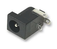
For the DC power socket (figure 3) cut a small aperture approximately 8.5mm x 5.5mm up against the inside end face of the box. This will allow the end of the socket to sit flush with the outside of the box. Fit by super glueing the flat side of the socket body to the inside end face of the box.
Solder the red (positive) and black (negative) voltmeter wires to the socket making sure the polarity is correct with the red wire to the pin terminal.
 |
| Fig 3: PCB mounting DC Power Socket |
DC Power socket 4 x 1.7mm
This size is not manufactured as a panel mounted socket so I used a PCB mounted version.
If you have a problem finding one please get in touch with me.
Figure 5 shows the front of the meter and figure 6 shows the relationship between an SLA battery's measured off load voltage and its state of charge.
 |
| Fig 4: Inside the box showing the back of the voltmeter and the back of the DC power socket to the left. |
 |
| Fig 5: Meter front with the power lead plugged into the socket at left. |
 |
| Fig 6: State of charge relationship to the off load battery voltage |


